
|
 |  |  |  |
| LITEF 104267 LED Display (Unknown Mfr.) | |
| Written by AnubisTTP on 2019-12-24 |
   |
| Description |
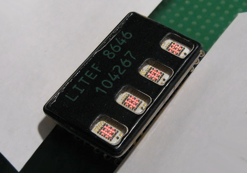
There are few collectors or electronics enthusiasts who would not stop and stare at this very unusual device. The LITEF 104267 is a 4 digit LED smart display that has been designed for aerospace applications, and it is packaged in a unique hermetic metal bathtub enclosure. The lid of the enclosure, which has likely been resistance welded into place for an airtight seal, is equipped with four small glass windows, which allow the LED dies inside to be seen. The display also has an eighth row of LED pixels with an unknown function located below each digit. These LED dots could act as a cursor indicator on large multiple line displays, or could have been included to allow question marks and exclamation points to be drawn more effectively. Unfortunately, the LITEF 104267 is a textbook definition of an undocumented part. Even the manufacturer is in question; these displays were probably made by Northrop for use in fabulously expensive military data terminals, but there is no concrete information to confirm this. Needless to say, there are no datasheets or manufacturer specifications available, and working out the pin connections for this LED display was a harrowing task.
| More |
Before we can figure out how the LITEF 104267 display works, we should probably take a moment to consider how it could work. There are several different ways in which a bitmapped LED display can be controlled. Fortunately, we can reject some of these possibilities out of hand by looking at the LITEF display externally. The display can not be direct drive because it only has 24 pins, which is not enough to control 7x20 lines of data. Segmented displays like the 5082-7000 are out; they use a false bitmap in which the center dies are not used and not installed. If the 1986 date code printed on the package is accurate, the LITEF display also likely does not use a combined character generator and shift register. Such a control scheme is, frankly, a pain to implement, and is typically targeted towards modern microcontrollers that are heavy on processing power but starved for IO pins. Microcontrollers were still black magic in 1986, it is unlikely a display from that era would be designed around the presence of one. So, is there another better documented display from this family of devices that could be examined to learn more about how the LITEF 104267 actually functions? The closest relative I have found is a prototype device called the Groves display, which was manufactured in 1973. As far as I know, the Groves prototype was never refined into a commercial product, but was a development project funded by the US military to produce a flat-panel replacement for 40 column computer monitors. The Groves LED display is an 8 digit device incorporating shift registers for both row and column selection. The rows have additional transistors to supply the high current needed for the LEDs, and resistors have been incorporated into the traces to eliminate the need for external current limiting. This seems a likely possible internal construction for the LITEF 104267 LED, but to determine which pins map to which functions, we are going to need to see what is inside the display's metal can enclosure.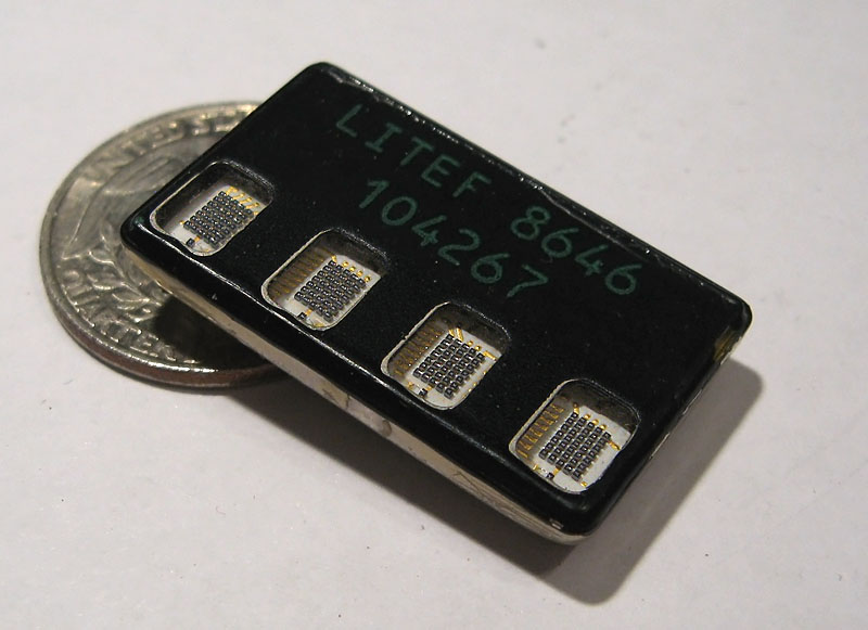
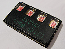
The LITEF 104267 LED display is a mysterious and undocumented device.
Segmented decoders: The display accepts a binary value, and displays the 7 or 16 segment pattern for that binary value. The overwhelming majority of segment decoder displays accept a BCD binary signal and display its decimal or hexidecimal value
Character ROMs: The LED display has a ROM chip inside with character patterns stored in its memory. The address lines for the ROM chip are brought out to pins and selecting a given address will cause that character to be drawn to the display.
Shift Registers: The row or column data is shifted serially into the display through a shift register which is used to 'scan' the display one row or column at a time. The opposing axis is typically brought out to pins and controlled directly.
Character Generator with Shift Register: The display has a character ROM whose address lines are connected to a shift register. Character addresses and digit positions are shifted into the display one bit at a time and stored internally.
Direct Drive: Both rows and columns are brought out to individual pins and all display logic must be provided externally.
Various smart LED drive examples. From top left; Hewlett Packard 5082-7000 LED, Siemens MDL2416, Hewlett-Packard HDSP-2001 LED display, Hewlett-Packard HCMS-3966, Monsanto MAN2 LED, LITEF 104267 LED display.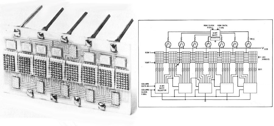
Groves LED display prototype.
Getting Inside the Can

LITEF 104267 LED display, cover removed. Image originally taken by Patrick Hickey.
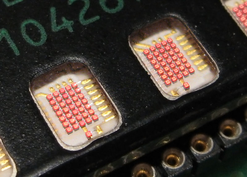
Fortunately another collector, Patrick Hickey, sacrificed one of his LITEF displays in the name of science. He used a file to carefully remove the lid from the display and then took a high resolution photo of the internal construction, which he posted to a project on hackaday.io. From this photo it can be seen that there are 7 driver ICs inside the LITEF 104267, of two different types. It can also be seen that least some of the LED rows in each character are tied together and brought out directly to pins on the package, which pretty much eliminates the possibility that the LITEF displays have a built in character generator.
Zoom in and enhance!
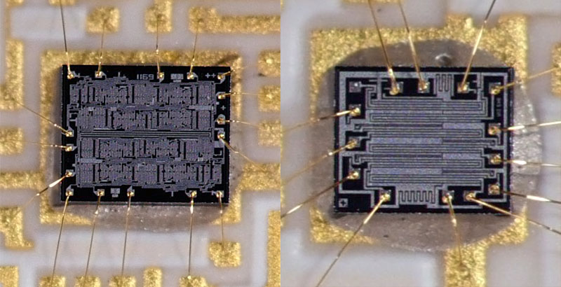
If we zoom in on the two chips and look at the top structures, the leftmost chip is very likely an 8 bit shift register. The 8 repeating structures in the top material are a dead giveaway, this is a common feature of shift registers used in LED displays. The integrated circuit on the right is more mysterious; there is little suggestive in the top material other than two zigzags that could be internal resistors. Each chip is situated above a LED digit however, and appears to be directly connected to the LED columns. This strongly suggests that they are current sink inverters; most logic chips are much better at sinking current than sourcing it, and a display with as many LED dies as the LITEF has is likely to have a high current draw. These four chips most likely convert the wimpy positive logic from the shift registers into the beefy negative logic needed to power a row of LED dies.
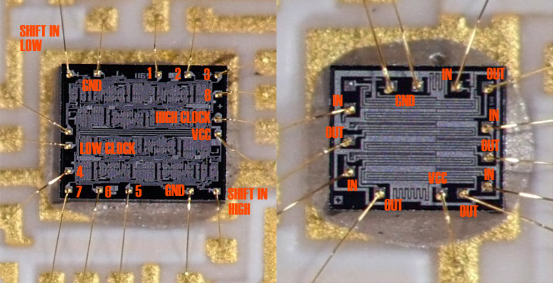
LED driver ICs, now labeled.
Based on these assumptions and the way the chips are connected inside the device, we can deduce the likely connections for each of the dies. Of particular note is that the leftmost 8 bit shift register is wired differently than the other two, which suggests that these are actually two 4 bit shift registers sharing the same die. Three 8 bit shift registers would yield a word length of 24 bits, but only 20 bits are needed to cover every column of LED dies. The low 4 bits of the final shift register are unused and unconnected, and the input signal is routed to the high 4 bits through a secondary connection. In the other two shift registers, a bond wire directly connects this high input pad to the last bit of the low register.

Diagram of drive signals for this display.
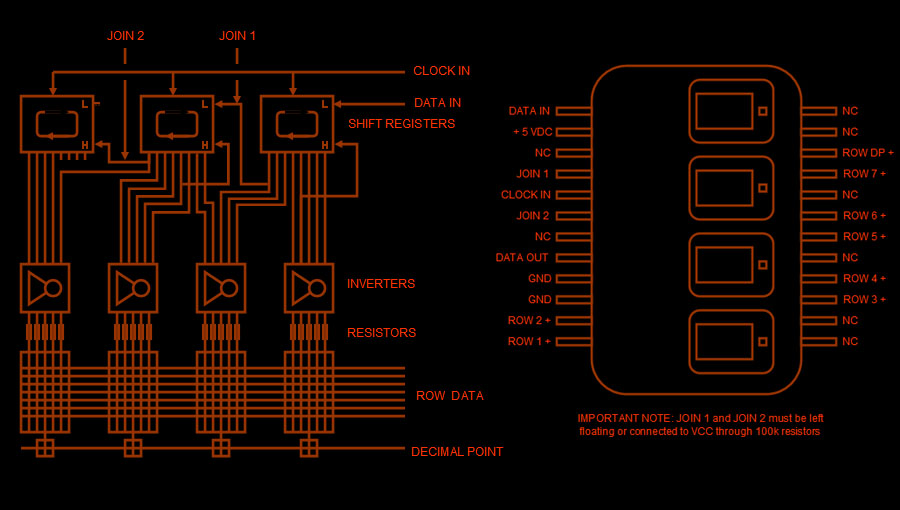
LITEF 104267 LED display, reverse-engineered block diagram and pinouts.
Based on these observations and assumptions, we can draw a likely block diagram and pinout for the LITEF LED display to show what is going on inside. The joins between the three shift registers have been brought out to external pins, likely for testing purposes during manufacture. This adds an extra wrinkle however, pins 4 and 6 must be left floating or pinned with resistors. If they are tied to ground, the internal shift registers will always see a logic level '0' on their inputs and will not pass through data. I am also making the potentially dangerous assumption that this display contains internal resistors and no external ones are required. This is an educated guess; if there are resistors they are buried beyond view in the ceramic substrate, but nearly every other smart LED display contains resistors, so it is logical to assume they are there even if we can not see them. The only thing left to do is hook up the display and see if the pinouts are accurate.
Let there be light!
A success, with the help of a microcontroller it is now possible to draw characters to the display. The drive scheme is fairly simple, a single bit is 'scanned' across each column through the shift registers to make it active, while each vertical row of pixels is sent to the row pins in sequence. There are a few questions still unanswered, in particular what the maximum serial speed is of the data sent to the internal shift registers, but if the LITEF 104267 was really used in 40 column computer displays, its maximum speed is likely to be fairly high. All said, it was quite a chore to reverse engineer this display just to get a few pictures of one in operation, but at least if another builder ever finds one of these LITEF LEDs and want's to use it in a project, they will not have to gamble with releasing the magic smoke to get it to work.
LITEF 104267 LED display.

LITEF 104267 LED display.
 Return to Solid State & LED Displays
| ©2000-2026 Industrial Alchemy. All rights reserved. | Switch to mobile version | Contact | |  |